Image

AS7240 22A PSU V2
Power Supply Specification
| Primary Supply Option | Maximum System Load (full charging capability) | Maximum System Load (reduced charging capability) | Charging Output Current |
|---|---|---|---|
| 5 Amp (Nominal) | 2.7 Amp | 4.5 Amp | 2.1 Amp |
| 11 Amp (Nominal) | 8.25 Amp | 10.5 Amp | 2.1 Amp |
| 22 Amp (Nominal) | 15.5 Amp | 21.5 Amp | 5.2 Amp |
Fault Indication Table
| Fault | LCD Message
(Keyboard-Display) |
Comments | Controller Code (Local 7 segment display) | Fault Relay
De-energised |
|
|---|---|---|---|---|---|
| Standalone Mode | Panel Mode | ||||
| Mains Lost | Mains Supply Fault | Occurs when input DC supply is less than 19.8 V. Clears when supply voltage is greater than 20.8 V and is stable for at least 1 second. | '1' | Y | N |
| Supply Low Voltage | Charger Low | Occurs when input DC supply falls below 25.2 V. Clears when supply voltage is 26.2 V or higher continuously for at least 1 second. | '2' | Y | N |
| Supply High Voltage | Charger High | Occurs when input DC supply is greater than 29.5 V. Clears when supply voltage falls below 28.5 V. | '3' | Y | N |
| Battery Missing | Battery Disconnected |
Occurs when battery connected is less than 19 V or battery voltage falls below 19 V. Cleared when battery voltage is equal to 20V or higher.
Fault codes 'b' and '6' look similar.
|
'b' | Y | N |
| Battery Low | Battery Low | In normal operation, a battery low fault occurs when the mains supply is missing and battery voltage is between 20V and 22V. The fault is cleared when the battery voltage is 23 V or higher.
During autotest (in both panel and standalone modes), a battery low fault will be indicated when the voltage drops below a threshold range of 19V and 0.9 x float voltage. When the battery voltage goes below 0.9 x float voltage, the auto test will be aborted and the battery low fault will be latched. |
'L' | Y | N |
| Charger Fault | Charger Fault | In normal conditions, this fault occurs when charger voltage is below (0.9 x float voltage) or greater than 29.5V with mains supply present, where float voltage is based on current battery temperature.
Charger fault clears when charger voltage is greater than (0.9 x float voltage) + 1V (AS7240.4 - 5.4d). In boost charge mode, this fault is indicated only when the charger voltage is greater than 29.5volts. |
'5' | Y | N |
| External Temperature Sensor Missing | Temp Sensor |
Occurs when there is a read error from external/internal temperature sensor. It is not limited to only the external temp sensor. It can also occur when the external temperature is missing or not connected.
Fault codes 'b' and '6' look similar.
|
'6' | Y | N |
| DC Out Indication | Occurs when output DC voltage is below 24.4 V or higher than 29.0 V. This state will only be indicated on the PSU's 7-segment display. It is not a fault condition and will not activate the fault relay.
Clears when output DC voltage is in the range 24.7 V – 28.7 V Will not occur during automatic 'Battery Capacity' test. Will not occur if the mains is missing. |
'7' | N | N | |
| Battery Charger Current High | Current High | On PSU H/W version 1.x Occurs when charger draws more than 4 Amps for 30 seconds. Clears when current drawn is below 4 Amps for 700 mSec. When the charger current increases more than 2 Amps for 5 seconds, the software reports a current high fault. On PSU H/W verions 2.x Except the threshold values across different product variants the logic to set/clear the fault remains the same. For 5A/11A variant: Charger high threshold is set to 3.5A For 22A variant, charger threshold is set to 6.5 A |
'8' | Y | N |
| Charger Comms Lost | Comms Lost | Occurs when the communications between the panel and the charger board is lost for 10 seconds. | '9' | N/A | N |
| Charger Program CRC failure | Program CRC | Occurs when computed CRC value is not the same as the value stored in flash memory. | 'C' | Y | N |
| Load Shutdown | Output DC voltage is cut off when mains supply is missing and battery voltage falls below 13.5 V.
Clears when mains supply is turned on or battery voltage is .22V or greater. |
'F' | Y | N | |
| Auto Test | Not a fault. Just an indication on 7 segment display of charger controller. Occurs when charger controller goes for auto-test. This test is run for 40mins.
The test will automatically abort if
|
'A' | N/A | N/A | |
| Watchdog Reset | Occurs when the most recent reset of Charger Controller was due to watchdog failure | 'd' | Y | N | |
| Trickle Charge | On PSU H/W version 2.x Only indicated on 7-segment display and not present on 485 data output. PSU enters trickle charge mode when system current exceeds the thresholds list in Table 14‑4 ).The PSU switches back into normal charging mode when system current falls below the thresholds listed in Table 14‑4. |
't' | N/A | N/A | |


- The decimal point of the 7-segment display will toggle every half second (500ms On, 500ms Off) in Normal Charge mode and be on, steadily, when the charger is in ‘Boost Charge’ mode.
- In Panel Controlled mode, the fault relay will operate (de-energise) only in the case of complete PSU failure.
- In Standalone Mode, the fault relay will de-energise for all PSU fault except ‘DC Out’.
Switch SW1 Operation
Historic Defect Mode.
This mode is initiated when the switch is pressed for 1 to 2 seconds. The Charger Controller will cycle through all the historic defect states since power-up and display it on the 7-segment display (refer to above Table). In this mode the decimal point on the display will flash rapidly (200ms On/Off). After 30 seconds the 7-segment display will come out of this mode. If there has been no historic defects since power-up, this mode will last for 5 seconds.
Auto - test Mode
Auto-test is only valid in the Standalone mode. In this mode, initiated when the switch is
pressed for 3 to 5 seconds, the charger will either start or stop the 24 hour test. The decimal
point on the 7-segment display will flash normally (500ms On/Off).
Charging Modes
Depending on the hardware version, the Charger Controller can operate in either two or three
charging modes. Hardware version 1.x has 2 charging modes and version 2.x has three.
With version 1.X, when the charge current
- Is below 250mA for more than 10 seconds, the charger controller enters the ‘Normal Charge’ mode.
- Is greater than 500mA for more than 10 seconds, the charger controller enters the ‘Boost Charge’ mode. It leaves this mode when the charge current drops below 500mA for more than 60 seconds.
With version 2.X, when the charge current
- Is below 500mA for more than 60 seconds, the charge controller enters the ‘Normal Charge’ mode
- Is greater than 1A for more than 60 seconds, the charge controller enters the ‘Boost Charge’ mode. It leaves, or exits, this mode when the charge current drops below 500mA for
more than 60 seconds.
| Hardware Version | Normal Charge Mode | Boost Charge Mode | |
|---|---|---|---|
| Entering threshold | Exiting threshold | ||
| Version 1.x | Charge current < 250mA,
for > 10 secs | Charge current > 250mA,
for >10 secs | Charge current < 250mA,
for >10 secs |
| Version 2.x | Charge current < 500mA,
for > 60 secs | Charge current > 1A,
for > 60 secs | Charge current < 500mA,
for > 60 secs |
Normal Charging Mode
In this mode:- The float voltage is temperature compensated. Temperature readings are gathered from sensor every 10 minutes.
- The regular ‘Battery Presence’ check is performed 15 seconds after bootup, then once every 60 seconds during normal operation
- The ‘Battery Capacity’ check (or ’24 hour test’) is run once per day (in Standalone mode) or when initiated by the Panel
- Actual battery voltage will be reported to the Panel (in panel mode)
- The decimal point on the Charger Controller 7 segment display will flash once a second
Boost Charge Mode
In This mode:- The float voltage is boosted to its maximum value (approximately 28 volts). There is no temperature compensation.
- The Charge Controller can operate in this mode for a maximum of 24 hours
- The ‘Battery Presence’ check is suspended until the charger comes out of the ‘Boost Charge’ mode
- The ‘Battery Capacity’ check
In version 1.x, the first ‘Battery Capacity’ check after the controller enters the ‘Boost Charge’ mode is ignored, both in Panel and Standalone modes, but all successive test will be performed.
In version 2.x, in order to ensure that the batteries are charged for the entire ‘Boost Charge’ duration (max 48 hours), the controller will ignore all the ‘Battery Capacity’ checks. This occurs in both Panel and Standalone modes. - After 48 hours, the charger controller will exit the ‘Boost Charge’ mode, even if the charge current is greater than the respective threshold limits. It must return to the ‘Normal Charge' mode before it can enter the ‘Boost Charge’ mode again.
- Battery voltage will be reported as equal to the charger voltage.
- The decimal point on the Charger Controller 7 segment display will be on continuously
Trickle Charge Mode
Note: The ‘Trickle Charge’ mode is implement only in hardware versions 2.x
When the system current exceeds a particular threshold (refer to Table below), the Charge Controller enters the ‘Trickle Charge’ mode. It exits this mode, and returns to the ‘Normal Charging’ mode, when the system current consistently drops below the threshold listed in Table below for over 60 seconds.
| Product Variant | Entering Threshold
(hardware controlled) | Exiting Threshold
(software controlled) |
|---|---|---|
| 5 Amp PSU (2.1 A Charger) | 2.9 Amp | 2.5 Amp > 60 sec |
| 11 Amp PSU (2.1A Charger) | 8.5 Amp | 7 Amp > 60 sec |
| 22 Amp PSU (5A Charger) | 16 Amp | 15 Amp > 60sec |
Charger Controller Option Settings and Indicators
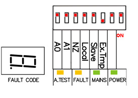 A DIP switch (SW2) is provided for configuring Charger Controller options.
SW2-1, Not Used, Off
SW2-2, Not Used, Off
SW2-3, Ex Temp, On To enable the external temperature sensor
SW2-4, Master/Repeater, Off
SW2-5, Panel/Local, Off
SW2-6, NZ/NO, Off
SW2-7, A1, Off
SW2-8, A2, Off
| Indicator | LED Details |
|---|---|
| A.TEST | Turns ON when ‘Battery Capacity’ test is operating |
| FAULT | Turns ON when a fault condition is present |
| MAINS | ON when mains is present |
| POWER | ON if Primary or Secondary power is available |
| FAULT CODE | 7-segment display. Refer to Fault Indication table for details |
External Fault Relay
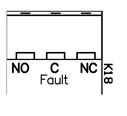 This relay provides a set of changeover contacts that can be used to indicate a fault condition to external equipment.
The relay is energised in the normal state and released to indicate a fault.
This relay provides a set of changeover contacts that can be used to indicate a fault condition to external equipment.
The relay is energised in the normal state and released to indicate a fault.
Note: In Panel mode, the Fault Relay will only operate (ie. de-energise) if PSU fails completely (as per AS7240.2-2204). Complete PSU failure occurs when the output voltage drops below 19V. It is cleared when the output voltage is above 20V.
In Standalone mode, the Fault Relay will de-energise for all PSU related faults except DC Out (Refer to the Fault Indication table)
Timed Power Relay
 This relay provides a set of changeover contacts rated at 5A @ 30V (resistive).
For charger controller firmware v1.04 and higher:
The relay is normally held in its energised state and released 30 seconds after mains power is missing. It is set back to its energised state when mains power is restored.
For charger controller firmware earlier than v1.04:
The relay will be energised 30 seconds after mains power is missing and release after mains power is restored
A typical application is to use this relay to disconnect door-holder devices during a mains failure to extend c.i.e operation time from the secondary battery supply.